In the first part of this post, we will take a look at STM32 microcontrollers, their history and the families of microprocessors and boards. The second part includes a step-by-step tutorial on how to set up Keil uVision, create a project and write code to blink the on-board LED on the NUCLEO STM32F103RB.
What is ARM?
The history of ARM
ARM was founded in the late ’90 as a subdivision of Acorn Computers. In that period, Acorn was producing desktop personal computers for the schools in Great Britain. Between 1982 – 1986, a small team within the company had been working on finding a processor on the market to comply with their requirements, but after a while they observed that such a product did not exist. They had therefore decided to build their own processor.
After the mother company had gone bankrupt, the division in charge with processors’ manufacturing created a new company in November 1990, under the name of Advanced RISC Machine. In just 18 months, they had successfully managed to both design and implement it, so that the first in-house built processor was running code on an Acorn machine in 1995. The computer’s initial name was Acorn RISC Machine. Nowadays, both the processor and the company are known as ARM, the latter being renowned for the wide variety of RISC (Reduced Instruction Set Computer) processors, as well as for other software and hardware products, developed in collaboration with global partners.
To be noted is that ARM does not produce their own silicone chips. They solely develop the architectures and then sell the intellectual property to manufacturers.
Where can the ARM processors be found?
ARM processors can be found in an extensive number of products, ranging from printers, gaming devices and hard-disks to washing machines, fridges or even robotic applications. Due to the wide usage, more than 30 billion ARM architecture processors have been sold, the figure continuing to increase, up to an estimated of 100 billion around 2020.

Source: www.arm.com
ARM family
The first processor in the ARM family has been ARM7TDMI-S, which is still incorporated in plenty of electronic devices, even though ARM does not commercialize licenses for it any longer. Starting with it, the processors have significantly diversified and improved, with models such as ARM9 or ARM11, continuously extending their field of applicability.
Nowadays, there are two main ARM processor families available, namely Cortex-M and Cortex-R. While Cortex-M family is designed to be used in microcontrollers, where the cost factor is crucial, Cortex-R comes up not only with more processing power, being able to complete more operations per second, but also with a more intricate synchronization mechanism, the interrupts having a limited and predictable execution time. All these features make the Cortex-R processors indispensable in embedded applications, e.g. hard-disk controllers, internal combustion engines etc., where time is a critical resource.
Another sub-family, Cortex-A, is frequently used on platforms requiring an operating system, like Linux. They incorporate complex memory management tools and an extended instruction set for multimedia applications.
ARM Cortex M
Due to the high optimization for embedded applications, and massive integration by manufacturers in microcontrollers, ARM Cortex M family has a reduced production cost. All versions, however, only implement Thumb instruction set (a compact alternative to the original ARM instruction set, with most instructions 16-bits long, and only a few 32-bits long).
- ARM Cortex M0 – Has a reduced number of logic gates, which translates into energy efficiency
- ARM Cortex M0+ – Besides the limited logic gates and efficiency, it is designed for energy-optimized embedded applications which also require many configurations. The instruction set is compatible with ARM Cortex M0, therefore the same compilator and debug tools can be used
- ARM Cortex M1 – 32-bit processor integrated in FPGAs (ARMv6-M Instruction Set Architecture), which offers high performance combined with small sizes
- ARM Cortex M3 – Low-power processor with reduced number of logic gates and small response time to interrupt requests. It is highly used in the automotive industry, as well as in industrial control systems
- ARM Cortex M4 – In addition to Cortex M3 features, Cortex M4F brings the advantage of floating point operations, for this reason being employed in signal processing applications
NUCLEO Boards
STM32 NUCLEO Boards integrate a STM32 microcontroller (32-bits µCs developed by STMicroelectronics, based on ARM Cortex M0, M3 or M4 cores).
STM32F103xx series is characterized by a frequency up to 72 MHz, 64 or 128 Kbytes of Flash memory and 20 Kbytes of SRAM, 16 channels for 12-bits analog to digital conversion, timers, SPI, I2C, USART interfaces.
Most of the examples presented from this point on will be based on NUCLEO STM32F103RB, which has an ARM Cortex M3 processor. The board contains two types of connectors: female pin headers, compatible with Arduino Uno development board, as well as male connectors, facilitating the access to all 64 pins of the microcontroller.
The upper part includes a ST-LINK programmer/ debugger with a SWD connector, which can be used both separately, and together with the NUCLEO board. At the same time, it can program or debug other STM32 microcontrollers as well, by simply cutting it away. Voltage is supplied either through the USB connector, or through an external voltage source (3.3V – 12V).
There are multiple boards in the NUCLEO family, each being designed for a certain purpose, starting from low-power to signal processing functions. In the figure below, a variety of NUCLEO boards can be distinguished, each containing a different target µC.
The development board is part of the NUCLEO-64 group. Following a simple convention, the number 64 comes from the total pins exposed in the integrated microcontroller, just as NUCLEO-32 or NUCLEO-144 use 32 or 144 pin microcontrollers.
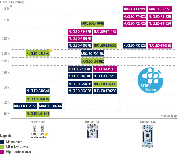
Source: http://www.st.com/en/
KEIL uVision IDE
KEIL is an integrated development environment created by ARM, which includes C/C++ compiler, a text editor called uVision and a sequence of debugging tools for various ARM-based microcontrollers. Our examples are developed in KEIL uVision 5, which can be downloaded here: https://www.keil.com/download/product/.
To start working with a board like NUCLEO, it is necessary to install on the PC a driver to recognize and communicate with it. The software is called ST-Link V2 and it can be downloaded from ST’s website, following the link: http://www.st.com/en/development-tools/st-link-v2.html.
Initializing KEIL
Right after installing KEIL environment, Pack Installer window will pop-up.
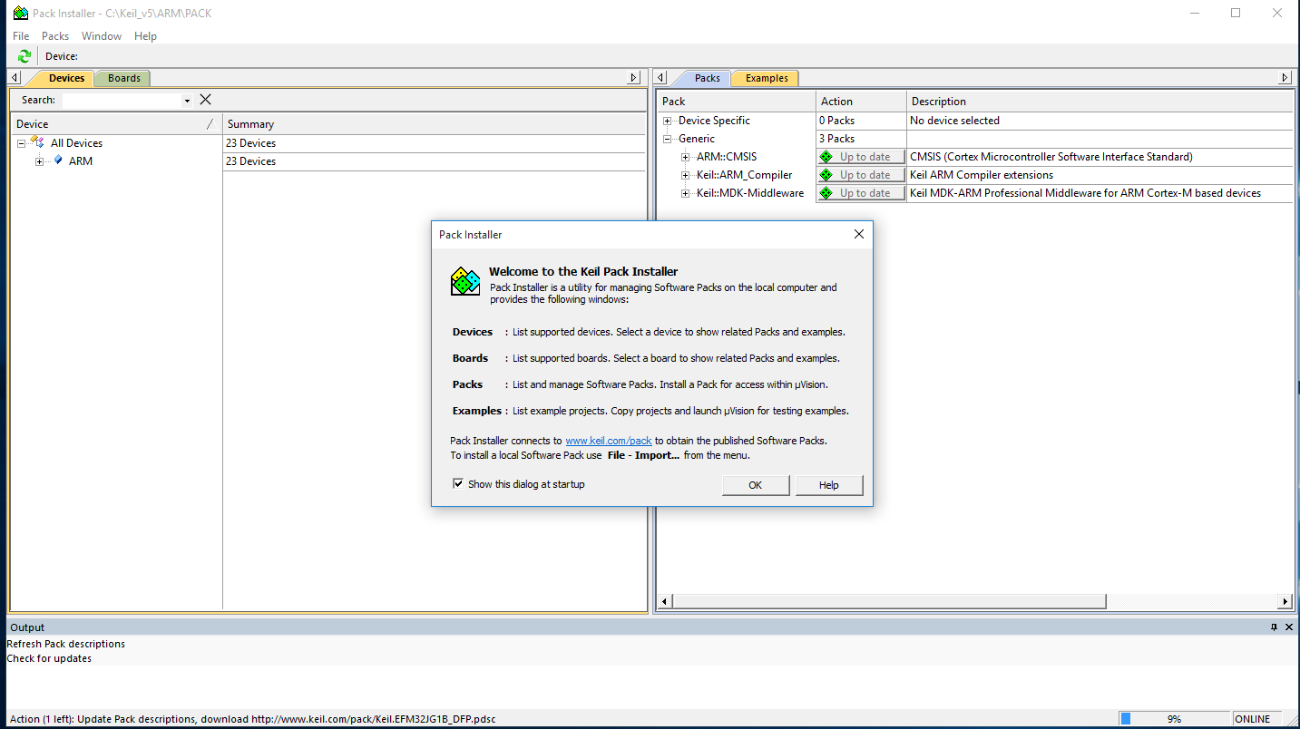
In the bottom right corner, you can spot a progress bar. KEIL automatically downloads a list containing all the boards or microcontrollers it supports, along with code samples and software modules. After this step has been completed, you will have to look in the microcontrollers list for the version you will be working on.
We will therefore select STMicroelectronics manufacturer, and STM32F103 in the submenu. From the second tab under Packs, you have to select KeilSTM32Fxxx_DFP and KeilSTM32NUCLEO_BARD, which will download and install hardware specific C libraries.

Creating a new project in KEIL uVision
Upon opening the IDE, you click the Project menu -> New uVision Project and select the target device, namely the microcontroller you will be writing code on. Click OK and you are ready to go!

The next window to appear is Manage Run-Time Environment, where multiple APIs can be included in our project. These APIs are of the utmost importance, since they contain functions and macros for working with peripherals, directly with the memory or even with the LEDs on the board.
First example
We will start with a blink example, which turns on and off the on-board LED with one second delay in between. For our code to run successfully, we need to include the modules highlighted in the picture below.
Startup, under the Device tab does not have to be missed, as it initializes the stack, the clock signal and multiple other peripherals, before the main() function is called.

If you ticked all of the above, you can happily create the file containing the main() function and start writing. In the Project window, expand Target 1 tab and right click the folder Source Group 1. Now just click Add New Item to Group ‘Source Group 1’

Select the type, name and location of your file and click Add. We will create a C file (.C), with the suggestive, yet unimaginative name “main”.
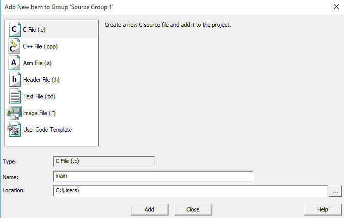
Code to be included in the C file:
#include "stm32f10x.h"
GPIO_InitTypeDef GPIO_InitStructure;
static __IO uint32_t TimingDelay;

void InitGPIO()
{
        RCC_APB2PeriphClockCmd(RCC_APB2Periph_GPIOA, ENABLE);
        GPIO_InitStructure.GPIO_Pin = GPIO_Pin_5;
        GPIO_InitStructure.GPIO_Speed = GPIO_Speed_50MHz;
        GPIO_InitStructure.GPIO_Mode = GPIO_Mode_Out_PP;
        GPIO_Init(GPIOA, &GPIO_InitStructure);
}

void InitTimer()
{
        SysTick_Config(SystemCoreClock / 1000);
}

void SysTick_Handler(void)
{
        if (TimingDelay != 0x00)
        {
                TimingDelay--;
        }

}

void Delay(__IO uint32_t nTime)
{
         TimingDelay = nTime;
         while(TimingDelay != 0);
}

int main()
{
        InitGPIO();
        InitTimer();

        while(1)
        {
                GPIOA->BSRR = GPIO_Pin_5;
                Delay(1000);
                /* Reset PD0 and PD2 */
                GPIOA->BRR  = GPIO_Pin_5;
                Delay(1000);
        }
}
As mentioned before, our code will intermittently light up the board LED attached to Port A, Pin 5. For this to happen, we will need to configure SysTick to generate an interrupt every millisecond, when the counter has reached the value specified in the SysTick_Config() function. Since the STM32F103 runs at 72MHz, a division factor of 1000 will mean that the counter increases up to 72,000, then generates the interrupt, which is treated in the interrupt routine SysTick_Handler(). The Delay() function does nothing else but to set the globally declared variable modified by the handler, TimingDelay, to the desired time to wait in milliseconds and wait for it to become zero.
For uploading our code to the board, the target needs to be set properly. We therefore click Options for Target… button, and in the Debug tab we select ST-Link Debugger from the drop-down list aside Use, according to the image below.
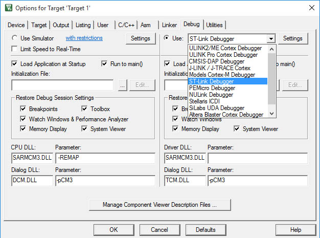
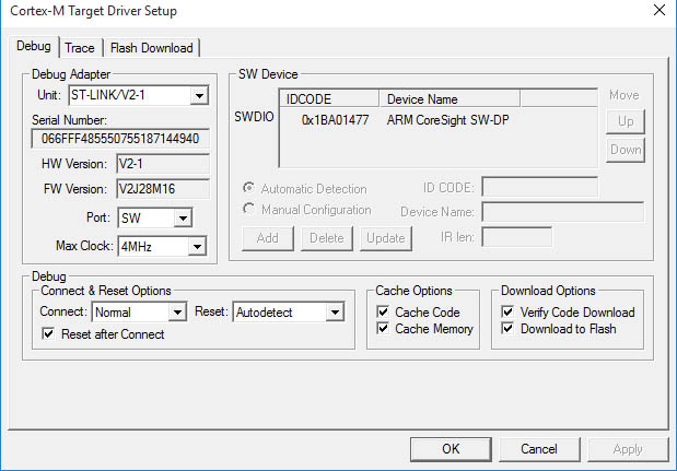
After that, we will press Settings button from the same tab and in the Download Options section both Verify Code Download and Download to Flash need to be checked. Click OK afterwards.
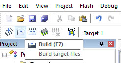
Before downloading the code to the board, it has to be compiled first, by pressing the Build button in the upper left side corner.
Upon successfully building, and connecting the board to an USB port of our computer, we can load the created binary file in the flash memory of our board by pressing LOAD. And done, the LED should blink with a frequency of 1 Hz.